/Projects/Reverse GeoCaching - GeoGame v1
This is my version of the Reverse GeoCaching box named GeoGame, based on Atmel AVR microcontroller.

Finished device connected to USB
All project files are available for download by clicking on the red download button below (open source hardware).
UPDATE: GPS conversion instructions are here.
It features:
- unlimited number of GeoPoints/Levels - (actually limited by amount of EEPROM memory on chosen AVR)
- USB connection to PC for GeoPoints upload and game setup
- PC application for GeoPoint uploading (programming)
- internal Li-Ion battery rechargeable via USB cable
- low-battery alarm
- emergency box open by password input
- "breathing" of LCD backlight - the "play me" reminder
- Level Codes - every GeoPoint has a 4-digit level code
- single button operation (play mode, menu mode)
- open source hardware, AVR GCC
The idea was to make a Reverse GeoCaching box with custom hardware and cheap parts. So, the hardware consists of:
- graphic display from Nokia 3310 (or 5110...) phone with backlight (or any other similar LCD based on PCD8544 driver)
- Li-Ion BL-5C battery from Nokia phone (or similar)
- MAX1811 Li-Ion charger IC
- PC USB GPS receiver from DealExtreme, that also has internal FLASH memory to record the trip and has USB-UART(TTL) converter on board that is hacked and used to interface the entire device to PC. Another bonus is the car-charger that comes with this GPS device which is useful while playing the game and driving around!
- ATmega328P (ATmega168 can be used with optimized code)
- "Mini Servo" from DealExtreme
- everything is powered by 3.7V battery, even the servo motor
- other misc. parts
The locking mechanism
The locking mechanism is made with a tiny servo motor mounted on a lower part of the box and a piece of metal that is bent in a particular shape and mounted on the box's lid. When the box closes, the servo's plastic thingy "goes" into the metal piece and therefore locks the box. This might not be the best locking method but it works just great. The box is not made to be safe so you could open it with a hammer or a screw-driver for example - it is wooden so use your imagination if you want to brake it open. The servo is controlled by PWM signal from the AVR microcontroller and yes, it works on lower voltages than 5V, it actually works normal at 3.6V!

Servo on lower part of the box

The metal piece on the lid of the box

Close-up of the locking mechanism
The LCD
I didn't want to go with standard 2x16 character LCD, simply because they are not fun and because they don't work (well) under 5V. I have a few scrap phones here - all Nokia, and they pack loads of great components. In this project you can see: LCD, Li-Ion battery and battery connector that came from these phones. The LCD panel was taken out of the phone but it still missed the "mating" PCB under it. So I designed one with six bright white LEDs (you guessed it - also from Nokia), one (required) capacitor (also SMD) and made it all fit.

LCD panel's mating PCB
You can buy this LCD with mating PCB and with backlight for very little money online. Anyway, the three LEDs are connected in series and in parallel with another three serially connected LEDs. So I needed three times of about 2.5V to power the backlight and that's why I designed a power booster to generate about 9V from battery voltage of 3.7V.

Schematics of LCD backlight power booster circuit
The gate of MOSFET is connected to hardware PWM output of AVR, and this way we can control the backlight brightness. If you end up using a normal LCD backlight circuit (powered just by VCC) you can connect those LEDs directly to PWM output of AVR and drive it from there. Maybe a small signal transistor might a good idea (actually mandatory) to drive the backlight in that case. In my circuit I used uPA1700 MOSFET from an old PC mainboard, but you can use any other N-type MOSFET suitable for power boosters.

Woodwork

LCD mounted on the lid of the box

Close-up of the LCD with backlight on

Trying to make things look nicer with a bit of black Silicone

Finished outside look
GPS receiver
This little thing gave me lots of problems. If you are going to build this device, I strongly suggest you go and purchase a stand-alone GPS module like this one. In that case you will also need USB-UART(TTL) converter.
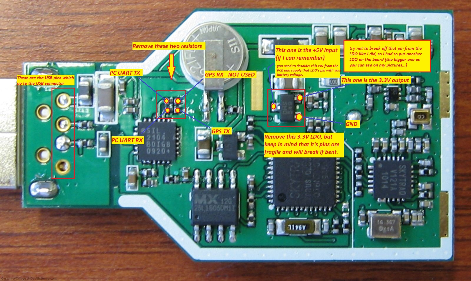
Anyway, the GPS receiver I used here has SkyTraq Venus chipset, and is actually very very good with sensitivity. Once it gets a lock it works even indoors. If you decide to purchase this one you will need to desolder two 0402-sized SMD resistors, and one tiny 3.3V LDO from the PCB. The conversion instructions are here.

DATA and POWER connections re-routed

Just need to solder the USB pins now...

Completed GPS conversion, secured in a heat shrink tube
The idea here is to intercept the connection between GPS chip and USB-UART(TTL) converter (the DATA connection), and to break the connection from the 3.3V LDO that powers the GPS chip (the POWER connection).
1. With the DATA connection we need the TX line from the GPS chip, and TX & RX lines from the USB-UART(TTL) chip. The TX line from the GPS chip goes to the Schottky diode and into the RX pin of Atmel AVR. The TX line from the USB-UART(TTL) chip goes to another Schottky diode and into the same RX pin of Atmel AVR. This way we can receive data from both the GPS chip and the USB-UART(TTL) converter chip. The remaining RX line of the USB-UART(TTL) chip goes into the TX line of Atmel AVR and is used to send data to the PC. Note: we don't need the GPS chip's RX line, so it is left floating (open).

The connector for serial communication and the external power supply to the GPS
2. The POWER connection of the GPS chip is re-routed to the P-type MOSFET (uPA1712) on our electronics. We simply power GPS's 3.3V LDO with our battery through the P-type MOSFET. This way we can turn the GPS receiver chip on and off.

The connector for USB that is used to communicate: PC with on-board USB-UART(TTL) converter IC
Now, when we want to communicate with PC, we simply turn off the P-type MOSFET - cutting the power to GPS chip. When we want to communicate with the GPS chip (actually receive data from it) we just turn on the P-type MOSFET. This actually gave me a bit of a headache because when I cut the power to the GPS chip, it pulls it's TX line to GND occupying the RX line of my AVR. I really thought that it would pull it's TX line to high impedance - just like any other normal IC (just like the on-board USB-UART(TTL) chip does when there is no USB connection), but no. This was fixed by inserting a switch on GPS's TX line that I flip during the GeoPoint programming. Maybe other GPS receivers are better, like one I suggested above, especially because it has "enable" pin (pin 1). In this case, you actually don't need the P-type MOSFET because this "enable" pin shuts down the GPS receiver and doesn't consume any power. It can be controlled just by AVR's IO pin. I just wish I found this GPS before I ordered my USB GPS from DealExtreme.
AVR MCU & the PCB
The "brain" of the entire project is the AVR Atmel microcontroller. I used ATmega328P primarily because of its RAM capacity and the way I handle RAM data. This "brain" does it all: controls the LCD, checks the battery voltage and reports if it is low, checks the charger status, beeps the beeper, controls the GPS chip and the servo motor, and computes the distance between current GPS coordinate and the GeoPoint. It works on 3.3V that is provided with 3.3V LDO from AME Inc: AME880AEFTZ, but any other 3.3V LDO can be used in this project since it doesn't consume much power.
The AVR can be re-programmed by connecting the programmer to the ISP port (LCD & ISP PORT). The button and the LCD are also connected to this port.
There is also an unused 32.768kHz crystal on board. It can be used to make a RTC that can be automatically set every time a GPS gets a valid signal. With this option, the current time can be displayed on LCD while the game is not played, and many more interesting things can be made.
Source code is available for download.

The AVR part of the schematics
The PCB is made to fit the box - hexagonal shape, with some slots for the servo.

The PCB with SMD components - bottom side

The PCB with DIP components - top side

Fitting test

All connected, ready to re-mount the lid (the GPS's TX-line switch is not yet mounted)

Fake bottom (cardboard) mounted (now you can see that switch - left to the colored wires)
Programming the GeoPoints/Levels
Programming can't be easier with a "GeoPoint Maker" PC application and your favorite serial terminal. It simply generates a GeoPoint "string" that you send to the GeoGame box during programming. The GeoPoint Maker application is written in Delphi and here is the screenshot:

GeoPoint Maker - screenshot
Every GeoPoint consists of few "fields":
- setup part: first eight zeroes/ones in the resulting GeoPoint string are automatically generated by choosing the check-boxes for the last three options;
- latitude: there is not much to say about this;
- longitude: there is not much to say about this;
- threshold (in meters): the allowed distance you can be from the actual coordinate in order to solve the current GeoPoint/Level;
- presses: the allowed number of button presses before the box closes forever;
- Level Code: if enabled, the level code is displayed on LCD during play. The user can go to the "MENU" and enter the Level Code of previous GeoPoints if he/she wishes to return and re-solve it, or, enter the Level Code of some unsolved GeoPoint and skip a level (the Level Code is known only to the person who programmed them);
- Date/Time limitation: if enabled, the GeoPoint/Level must be "solved" before this timestamp or the box will be locked forever;
- Time Match (more than): if enabled, and if at the correct geographical destination, the GeoPoint can't be solved before this HOUR in that day;
To enter the MENU in order to re-program the GeoPoints, hold the button until the MENU appears:

Menu mode
Surfing around the menu is done by a short press of a button, and selection is done by a longer press. After selecting the "PC mode", a password input dialog is displayed and after the correct 4-digit password is entered, the box is unlocked and programming can take place (please see video of the programming in action).
Urban Quest (test)
Programming two GeoPoints
Author (sent by): Trax
Download counter: 455
Rating: 
 (2.30, votes 5231)
Vote: 

Date: 08-01-2011
Lokalna verzija ove stranice: Reverzni GeoCaching - GeoGame v1
Tags: atmega328, atmega328p, atmel, avr, booster, geocache, geocaching, gps, lcd, li-ion, max1811, nokia, servo. +add your tag
similar content
- Tiny Reverse GeoCache (16-09-2010) [@News]
- GeoGame project published (09-01-2011) [@News]


