comment [46]
- From jfmarque on 27-06-2014 at 18:41:10
Hi Trax.
Here in Mexico there are not ZD 1V diodes. There are only 2.3. Is it enough? Could you please
tell me the function that ZD are doing there?
IP: n/a
After putting together this little device, you must enter programming-mode to learn some phone numbers which this module will call after detecting an input on it's sensor pin.
After programming just supply power to the device. After pressing the button "Pokreni dojavu alarma" it will start to dial (tone or pulse, depending on the jumper setup). When the phone call is succesfully established, the called party should press pound key "#" to stop the device from calling another number or again.
UPDATE: Source code is now available for download!

You should put a sensor instead of button "Pokreni dojavu alarma".
Programming the numbers
- press the "program" button
- pick up the phone that is connected to the same phone-line as this device
- punch-in first number and then "*" key
- punch-in then next number and then "*" key
- punch-in the rest of numbers, if more, and finalise with "*#" (example: 061123123*061456456*#)
Please note: The device will learn 64 characters/digits including * and # keys.

Author (sent by): Trax
Download counter: 17,237
Rating: 

 (2.98, votes 4005)
Date: 17-02-2007
Lokalna verzija ove stranice: Phone call alert
Tags: controller, dtmf, line, phone. +add your tag
Do you have a part number for these Z diodes? Something like 1N5221B (2.4V ZD).
IP: n/a
Hi Trax.
Here in Mexico there are not ZD 1V diodes. There are only 2.3. Is it enough? Could you please
tell me the function that ZD are doing there?
IP: n/a
Here you can find my MikroC code for HT9200A (serial DTMF generator).
http://www.libstock.com/projects/view/879/dtmf-dialer-with-holtek-ht9200a-serial-mode
IP: n/a
Anyone got a working one of these they want to sell?
IP: 192.198.151.43
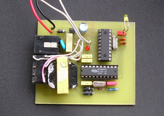
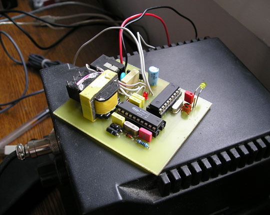
Above the relay in the circuit, the one marked with U4 is LM7805 voltage stabilizer. There is a
place for relay on the PCB, it is the 6 pin device between the PIC and the big capacitor. It is
not in that place on my PCB because I made mistake with pinout, so I had to move relay beside
the transformer with wires.
IP: n/a
Thanks for your sharing and it is so usefull for most of us...
I have a question,,,
there is a relay in the photo near the transformator but in pcb there is no place for relay...
and what is the device name in the photo which is above the relay in the circuit, I could not
understand what it is... :s
thanks again...
IP: 46.196.225.39
Da li postoji mogućnost upotrebe HT9200A ili HT9200B čipa (serial-parallel mode) ?
IP: n/a
Thank you again, I really appreciate that, please forgive me for that selves request, thanks
again.
IP: 46.35.88.123
Sosaif, I cannot make additional PCB design. I don't have time. There is a PCB design in the
project files (you downloaded it already) and you can open it with sPrint-Layout program (find
it on Google). Regards
IP: n/a
please Mr Trax reply for me if you could make the design more simply I'll be grateful.
this program can make the PCB automatically, it gives completion rate - of connection -.
I've constructed the circuit by this program but the PCB design correct connection was 71\%.
the program is:
http://www.mediafire.com/?tmidymmyyzm
and the circuit is in :
http://www.4shared.com/file/nW2N5Ajd/phone.html?
please post.
IP: 46.35.88.123
You can log-in on forum link: Login page. After logging-in, return to this page and click refresh in your browser.