comment [376]
- From trax on 17-03-2014 at 08:20:30
Turgut, yes it is. In that case you will loose wall-switch functionality!
IP: n/a
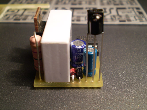
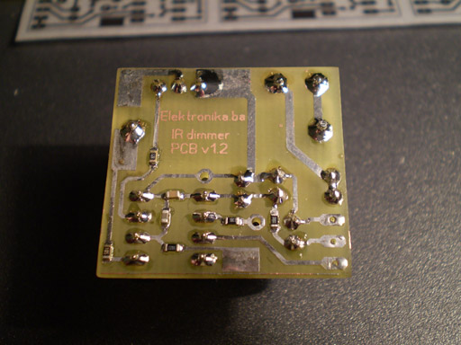
This is a very simple IR light dimmer that you will wish to have sooner or later, especially those who are lazy enough to get up and turn off the lights. There are two versions of PCB for two sizes of capacitors, so PCBs are: 32.5 x 26.5mm and 28.5 x 27mm.
You can download the project files at the bottom of this page by clicking on red "download" button.

Features of current beta version of firmware:
- Soft start (gradually turning on the light bulb)
- Soft down (gradually turning off the light bulb)
- Learning IR codes from RC5 and NEC remotes
- Dimming in 10 levels by using only IR remote
- Previous dimm-level remembering when operating with remote
- Sleep timer in duration of 1.6min for 60Hz version and 2min for 50Hz version
- ON/OFF control with wall pushbutton
Dimmer is connected to existing home wiring installation inside a junction box, which is usually located above the light switch. In order to properly connect the dimmer to installation one should follow the schematics provided for that purpose. If connected differently there is a very big chance of some freaky side effects such as burned PIC microcontroller, serious fire and who knows what else.
Learning remote control IR codes (programming procedure)
After connecting dimmer to installation you must program the remote control buttons. Here is how to do that:
1. Hold the wall pushbutton for 11 sec so that dimmer can enter programming mode. After those 11 sec, LED will start to blink fast, and light will dimm to third (3.) level. Now you have 11 sec to complete the programming sequence:
2. Press the first button on your remote that will increase light level or turn on the light when it is turned off (ON/UP)
3. Press the second button on your remote that will be used to decrease the light level (DOWN)
4. Press the third button that will be used for activating/deactivating sleep mode (SLEEP)
5. Finally, press the fourth button that will be used to turn off light completely (OFF)
During programming, both the light bulb and LED will blink to confirm IR code reception. If your remote control does not have all 4 buttons that you can use, you can repeat previous button but that will cancel out some features. For example, if your remote has only two buttons (A and B), and if during programming you press: A A A B, that means that key A will be used for ON/UP function, and key B will be used to completely turn off the light. If you choose combination A B B B, it means that the key A will be again used for ON/UP function, and key B will be used to decrease light level (it will also turn the light off completely in 10 button presses - until zero level).
Programming notice: If during programming, you notice that LED blinks even when you don't press any buttons on your remote control, it is probably because you used TSOP11xx instead of TSOP17xx receiver module. In that case, you will probably not be able to program your dimmer properly.
If you are not satisfied with your choice of remote controller buttons, you can repeat the learning procedure as much as you like.
If you are planning to use your TV's remote controller, you should probably choose those teletext buttons: red, green, yellow and blue to avoid, for example, switching channels when operating the dimmer.
Sleep timer
Sleep timer can be activated by a bit longer wall-pushbutton press, more than 1.8 sec to be precise, or by pressing the appropriate button on the remote controller. Sleep timer cancellation is accomplished just like the activation. It is possible to increase/decrease the light level when sleep timer is active. Dimmer will automatically set the light level to six (6) when entering the sleep mode, but only if previous level was greater than 6.

Important notice: This device is connected to mains power line, so it requires a lot of respect. If you are not sure in what you are doing, you better leave the installation part to the experienced electrician.
Dimmer in operation:
Note: Dimmer works better with TIC206 rather than TIC216!
Author (sent by): Trax
Download counter: 55,258
Rating: 

 (2.99, votes 8039)
Date: 07-02-2009
Lokalna verzija ove stranice: IR dimmer svjetla v1
Dear, Friend. I am trying to a light dimmer project like this one but using Contact buttons
for each function (on e button for light UP, One button for light down, the other button for
on/off).
I need to have also the source code so I can change the functions. I am willing to pay for this
project but my budget is very low. (I am a college student).
Please send me quote at my email or Skype: NWSTM.COM and nwstm@yahoo.com
Thanks a lot!
Marlon
IP: 98.194.144.38
Turgut, yes it is. In that case you will loose wall-switch functionality!
IP: n/a
Hello,
Is it possible to mount hole circuitry in lamp cover at ceiling?
IP: 78.189.178.139
hi friend,a person is selling your project in Argentina, I think that was not the purpose of
publishing the development d. Here is the link is in Spanish.
http://articulo.mercadolibre.com.ar/MLA-483664769-dm-control-interruptor-inalambrico-dimmer-a-c
ontrol-remoto-_JM
IP: 181.29.179.128
Zdravo Trax. Uradio sam sve po tvojoj sugestiji. Promenio polaritet izolacijskog trafoa,
napajanje PICa je dobro filtrirano, otpornik 1M za detekciju nule smanjen na 10K, i nista. Isto
se ponasa. Izludjuje me???
IP: n/a
Hello.My name is Paul and i am from Romania.firs of all your project is awsome!!!i buid the
firs version and work ok but now i want to build the second version with dimmer and i want to
use it on a powerfull led but at 12v and i don't know what is to do because i can't read the 50
hz from the network bbecause i want to use it on my solar baterry.i wonder if is possible to
writte the code without reading the 50 hz...Thank you verry much
IP: 86.126.19.98
Hvala Trax, probacu i javicu sta se desava,
Pozdrav.
IP: n/a
I da, ovaj otpornik od 1M sto detektuje prolazak kroz nulu smanji na 10k. Ako nista od
navedenog ne bude popravilo stanje, onda moras umjesto tog otpornika staviti sklop koji ce sa
transformatora detektovati prolazak kroz nulu i na izlazu davati samo 0/5V. Ali o tom po tom...
IP: n/a
Na ovom izolaciskom transformatoru 220/12 Tr1, obrni "polaritet" na primaru ILI
sekundaru. Znam da nema bas puno smisla ali probaj. Drugo, postoji mogucnost da ti se ovaj
MOC3023 ne aktivira kako treba pa malo probaj nastimati predotpor od 470ohm, smanji ga na 330
ili povecaj na 560 pa vidi sta ce se desiti. Inace, sve ostalo se cini da je OK. Dodaj i neki
elektrolitski kondenzator paralelno sa napajanjem PIC-a, mozda se on resetuje iz nekog razloga.
Stavi i tri kondenzatora od 1n 10n i 100n paralelno sa pinom 1 i 8 sto blize PIC-u.
IP: n/a
A evo i sheme:
http://tinypic.com/usermedia.php?uo=1LhMuIYoALxrxL\%2FcSjRYg4h4l5k2TGxc#.Umq83038K9I
IP: n/a
You can log-in on forum link: Login page. After logging-in, return to this page and click refresh in your browser.